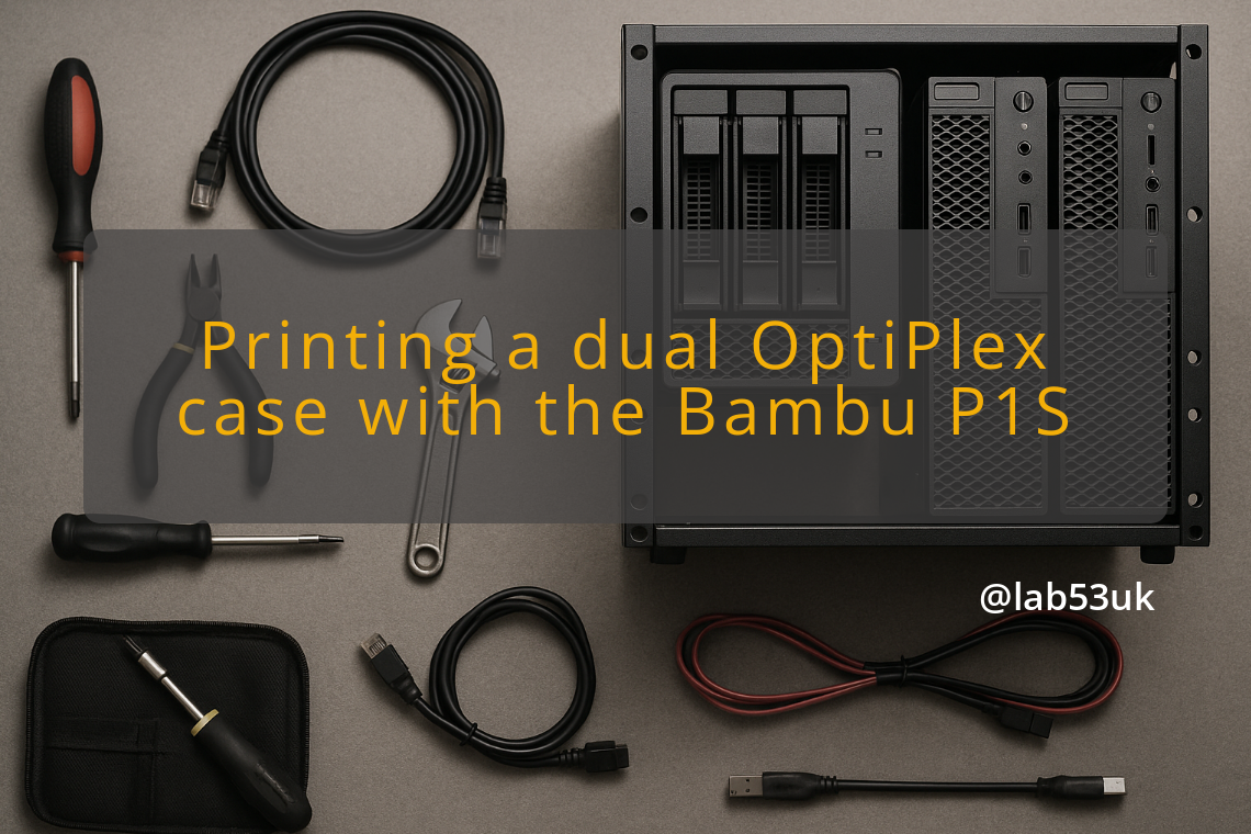
I built a dual OptiPlex homelab inside a 3D-printed shell. This is the bit that actually mattered: printing the case on a Bambu P1S, then fitting, wiring, and cooling two OptiPlex boards without turning the inside into a mess.
For the print, I used PETG-GF for strength and surface finish. The Bambu P1S handled the geometry cleanly. The main shell took about 15 hours on a single 0.4 mm nozzle. Print orientation matters, so I laid the broad flat faces on the bed to cut support time. I added heat-insert holes where the OptiPlex mounts meet the shell. Fuzzy skin on the visible faces helped hide layer lines. I kept wall thickness and infill up at load points, with 20-30% infill as a decent balance. A brim or raft helped with the larger thin sections, which wanted to move about. I fit-tested the boards and connectors before the final clean-up. Hot glue worked for small brackets during assembly, which is useful when cable space is tight. I packed fragile connectors with foam or PTFE tape where they might rub on the plastic. If you want to reuse the OptiPlex front panel, take the top cover off during disassembly and keep the original fastenings for a cleaner finish.
Power and cabling need planning from the start. I used one external 19.5 V 240 W laptop-style supply to feed both machines, with local buck converters per unit. That keeps the external cable count low and lets each buck converter provide the right rail voltages to its OptiPlex board. I labelled every cable. Short DC pigtails and heatshrunk joins kept the runs tidy. For ethernet, I used short internal leads to Keystone RJ45 couplers mounted at the rear of the case, then a single patch cable to the switch. Power stayed on one side and network on the other, which cut down on crossover. I routed cables through defined channels and held them with low-profile clips or zip ties. I kept mains cables away from SATA and front-panel headers. A small Arduino or other microcontroller handled basic automation well enough. Mine sits on a simple PCB and switches a 5 V Noctua 92 mm fan with a MOSFET, while also watching a buck converter output through a voltage divider to catch undervoltage. If you do the same, use isolated sensing and a logic-level MOSFET for fans or relays. I used heat inserts at PCB mount points and M2 screws on the small headers.
Cooling matters more than people expect in a dual layout. Airflow gets cramped fast. I made a clear intake and exhaust path, then used a single 92 mm 5 V Noctua to pull air out the back. The fan sits downstream of both CPUs so it draws through the main vents. The PSU and buck converters live in a partitioned area with small vents. I added thermal pads on any board or power part that sits close to the plastic wall. Fan direction is worth checking twice before final assembly. For temperature monitoring, lm-sensors or the vendor tools from each OptiPlex do the job. I did not rely on one sensor near the fan; CPU and VRM temperatures both matter. If temperatures run high, a small duct or a second low-speed fan can push air over the VRMs. Quiet fans with higher static pressure suit tight ducts, while high-CFM fans work better in open flow.
Testing took time, and it should. I checked for shorts and correct voltages at the buck converter outputs with a multimeter before connecting any motherboard. Then I powered each OptiPlex one at a time, checked POST, and set the BIOS boot order and wake-on-LAN settings. For networking, fixed IP addresses or DHCP reservations made the automation scripts reliable. I wrote a small SSH-based controller for graceful shutdowns, reboots, and updates. Where remote power cycling was needed, I used a relay triggered by the Arduino or a smart PDU in line with the main supply. For troubleshooting, I followed the same checklist every time: external supply voltage, buck converter output under load, fan spin and direction, then a 30-minute stress test on each CPU to catch throttling. I recorded voltages and temperatures during the test. I kept spare DC plugs, short ribbon cables, zip ties, and a tube of silicone or hot glue nearby. The printed case did improve airflow over the stock layout once the ducts and exhaust were in place. The cable work was worth it.