How I Enhanced My Home Lab Security with VLAN Segmentation
What you’ll build: VLAN
Overview of VLAN Segmentation
I split my single flat network into several logical networks using VLANs. Each VLAN isolates traffic at layer 2 so devices on one VLAN cannot see devices on another without explicit routing. That isolation gives me control over which systems can talk to which, without buying extra hardware.
VLANs are a networking feature available on most consumer and prosumer routers and switches. You tag or untag traffic on ports or trunks and map VLAN IDs to IP subnets. I used simple, repeatable rules so the setup stayed tidy and easy to audit.
Security Benefits of VLANs
Segmentation reduces blast radius. If a guest laptop gets compromised, it cannot reach my lab servers if it sits in a guest VLAN. I keep IoT devices in their own VLAN, isolating their noisy behaviour from critical systems. VLANs also let me apply more restrictive firewall rules per subnet and monitor traffic more effectively.
This is not perfect defence. VLANs protect against horizontal spread and casual misconfiguration, not against an attacker who controls the router or poaches tagged traffic on a trunk. Treat VLANs as one layer in a defence-in-depth approach.
Expected Outcomes
After setting this up I had:
- Separate subnets for guests, IoT, servers and my workstation.
- Clear firewall rules preventing lateral movement between those subnets.
- Easier monitoring and targeted logging per VLAN.
You should expect improved isolation, simpler incident response and clearer traffic flows.
Prerequisites
Required Hardware
You need:
- A router or L3 switch that supports VLAN tagging (802.1Q).
- A managed switch for wired VLAN ports, or at least port-based VLAN support.
- Devices that can be assigned to VLANs (most do, either via DHCP on a tagged network or by physical port).
I used a small managed switch and a router with VLAN support. Cheap unmanaged switches won’t help unless you keep all VLANs separate physically.
Software Requirements
You need firmware or software that exposes VLAN configuration:
- Router OS with VLAN support (OpenWRT, pfSense, commercial vendor GUI).
- Switch management interface (web, SSH, or CLI).
- DHCP server that can serve multiple scopes per VLAN.
I run a DHCP scope per VLAN. If you use a router as DHCP server, assign a unique subnet per VLAN.
Network Configuration Basics
Each VLAN needs:
- A VLAN ID (e.g. 10, 20, 30).
- An IP subnet (e.g. 192.168.10.0/24).
- A gateway interface on the router for that VLAN.
Trunk ports carry multiple VLANs between router and switch. Access ports carry one VLAN to an endpoint. Keep the management interface off networks you do not trust.
Tested environment
Home Lab Setup
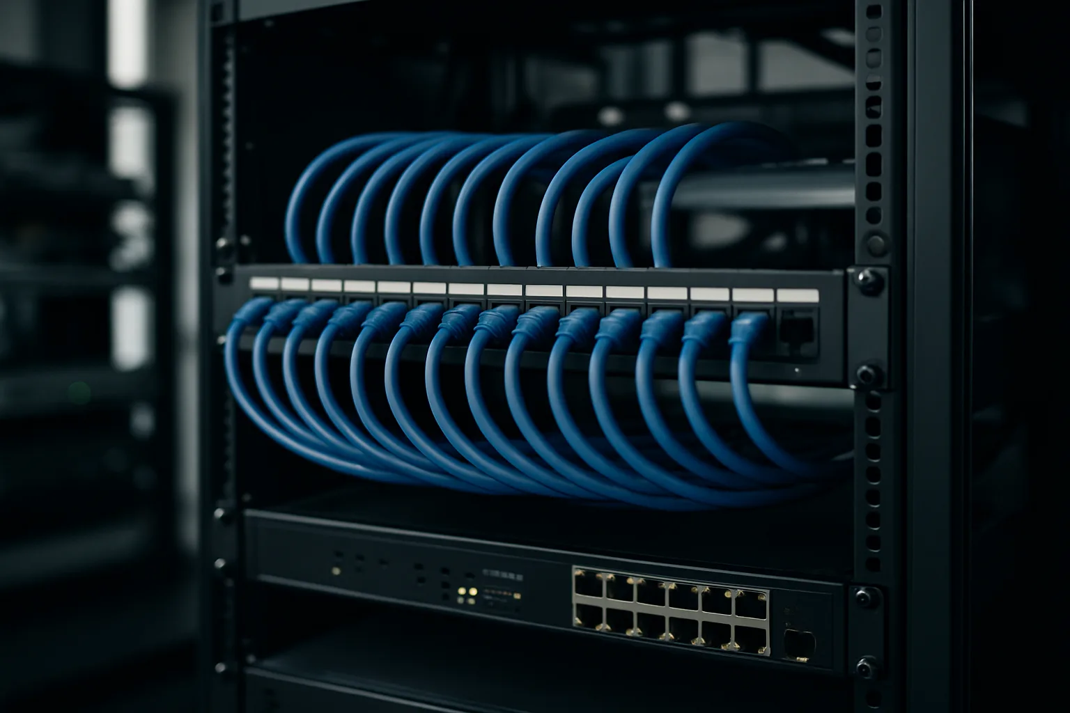
My home lab sits in a spare cupboard. I have a rack with a router, managed switch, a few servers and Wi‑Fi access points. The lab is physically separate from my living room devices, but both connect to the same core switch with VLANs enforcing separation.
Network Topology
- Router (VLAN-aware) — trunk to managed switch.
- Managed switch — access ports for servers, APs and a wired workstation.
- APs — broadcast multiple SSIDs mapped to VLANs for wireless clients.
I keep the router on a dedicated management VLAN so I can reach it only from trusted networks.
Devices Used
- Router with VLAN support (router firmware of your choice).
- Managed switch (8–24 ports depending on need).
- One or more APs that can tag SSIDs to VLAN IDs.
- Servers and a workstation. All devices were standard home-lab hardware.
Step-by-step: VLAN
Step 1: Accessing Your Router
- Log into your router’s admin interface.
- Back up the current configuration.
- Put the router into maintenance window if needed so you don’t disrupt others.
If you use CLI, open SSH. If web GUI, use HTTPS. Backing up first lets you revert quickly if something breaks.
Step 2: Creating VLANs
- Pick VLAN IDs and subnets. Example:
- VLAN 10: 192.168.10.0/24 — Servers
- VLAN 20: 192.168.20.0/24 — Workstation
- VLAN 30: 192.168.30.0/24 — IoT
- VLAN 40: 192.168.40.0/24 — Guest
- Create those VLANs on the router, assign an interface address for each (the gateway).
- Configure DHCP scopes per VLAN.
Verify each VLAN has a distinct subnet and gateway. If DHCP fails, devices will fall back to link-local addresses.
Step 3: Assigning Ports to VLANs
- On the switch, set trunk port connecting to the router to carry the VLAN IDs.
- Set access ports for servers to VLAN 10, workstation to 20, and so on.
- Configure APs to tag SSIDs to the correct VLANs.
Keep management ports on their own VLAN and consider using a non-default VLAN ID for extra obscurity.
Step 4: Configuring Firewall Rules
- On the router, deny inter‑VLAN traffic by default.
- Add explicit allow rules where necessary, for example:
- Workstation → Servers: allow SSH and specific ports.
- Guest → Internet: allow HTTPS, DNS.
- Block known risky flows from IoT to server VLANs.
Make rules explicit and minimal. State which ports and protocols are allowed. Avoid broad rules that defeat segmentation.
Step 5: Testing Connectivity
- From a device on each VLAN, test internet access and gateway reachability.
- From an allowed VLAN pair, test permitted services (SSH, HTTP).
- From blocked VLAN pairs, confirm connections fail.
Use ping and service tests. If a connection unexpectedly works, inspect firewall state and switch port tagging immediately.
Verification: confirm it works
Checking VLAN Configuration
Check the router and switch VLAN tables. Confirm:
- Correct VLAN IDs are present.
- Interfaces have correct IPs.
- Trunk ports list the right VLANs.
On managed switches, the show vlan or equivalent command should list access and tagged ports.
Testing Network Isolation
- Try pinging a server from an IoT device; it should fail.
- Attempt SSH from guest VLAN to servers; it should fail.
- Verify allowed traffic flows work as expected.
If a blocked flow works, capture packets on the router to see where the routing decision is made.
Validating Security Measures
Run port scans from less-trusted VLANs to ensure limited exposure. Check logs for denied traffic. Revisit firewall rules for any overly permissive entries. If you use IDS/IPS, ensure sensors are listening on the correct VLANs.
When a rule changes state from blocked to allowed, document why and for how long.
Troubleshooting
Common Issues
- Wrong VLAN tagging on trunks causes all traffic to land in the default VLAN.
- DHCP not served on a VLAN because the DHCP scope is missing.
- AP misconfiguration leaving SSID on the wrong VLAN.
- Firewall rules overriding intended behaviour.
Diagnostic Commands
On Linux or device CLI:
- ip addr / ifconfig — check interface addresses.
- ip route — check routing table.
- ping and traceroute — connectivity checks.
- tcpdump -i interface vlan and host filters — inspect traffic.
On switches, look for:
- show vlan
- show interfaces switchport
Resolving Connectivity Problems
- Confirm physical trunk connection between router and switch.
- Verify trunk allows needed VLANs.
- Check access ports are set to the intended VLAN.
- Validate DHCP scopes and gateway IPs.
- If firewall blocks expected traffic, add a temporary logging rule to see matches.
Change one variable at a time. Revert to the backup config if you get lost.
Wrap-up and next steps
Summary of Key Points
I used VLAN segmentation to isolate guests, IoT, servers and workstation. That reduced lateral movement and made traffic controls straightforward. The steps are: plan VLANs, create them on router and switch, assign ports, enforce firewall rules and test thoroughly.
Additional Resources
Use vendor docs for exact commands and GUI steps. Router and switch manuals will show VLAN and trunking specifics. If you want sample configs, look for OpenWRT or pfSense VLAN guides matching your hardware.
Future Enhancements
Next, I plan to add:
- Host-based firewalls for layered control.
- Centralised logging per VLAN.
- Network access control for critical servers.
Those steps tighten security beyond VLAN-based segmentation and help with auditability.


